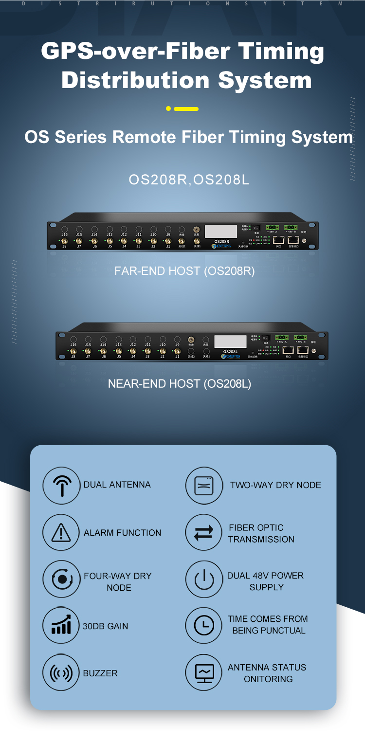
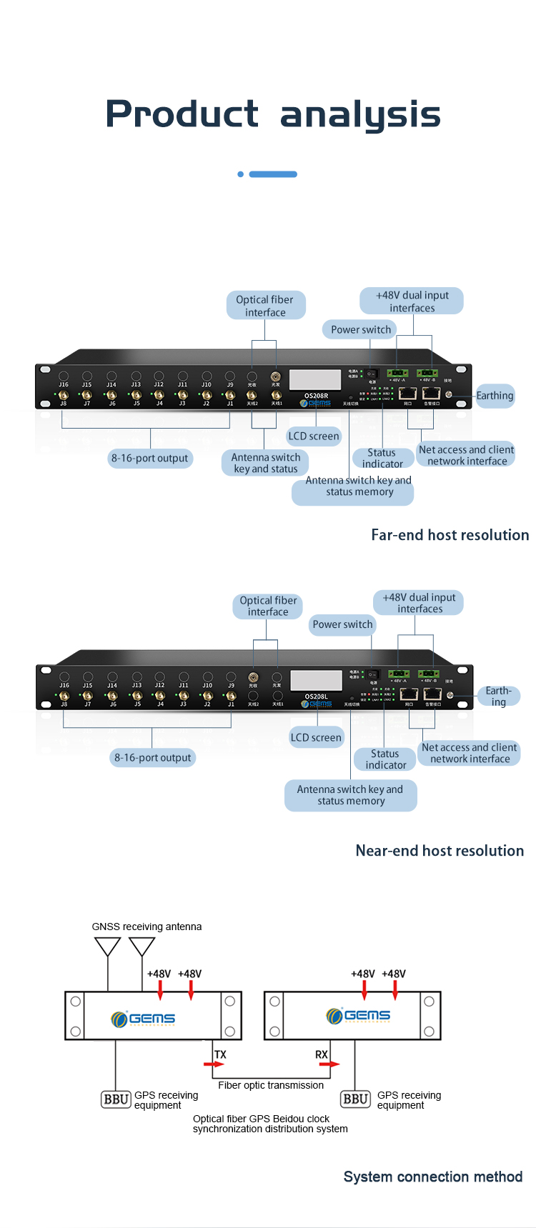
This system consists of far-end host and near-end host. The far-end host receives input through two ends and possesses 1 to 8 optional optical fiber interfaces through which signals are transmitted to near-end hosts. The near-end host outputs signals to GPS device through 1-8/16 ports. The satellite signals received by near-end host from the far-end host through optical fiber are amplified and distributed to the output ports, which, at the same time, offer GPS signals to 8/16 ports. After entering GNSS signal system management terminal and setting IP, this system can display the connection status of each port, number of visible GPS satellites and C/No value, number of visible Beidou satellites and C/No value, position, etc.
Optical fiber interface is used as an independent interface for signals transmission between far-end host and near-end host via optical fibers.
Operating Instructions
This system supports dual+48V power supply. After power on, the indicators of power supply A and power supply B light on. Two input ports of far-end host are connected to GPS antennas. Upon successful connection, antenna 1 and antenna 2 indicators are on. The optical fiber interface is round FC-APC interface. When the optical fiber module runs normally, the optical transmitting indicator light is on and the 8/12/16 output ports can be connected to BBU or GPS device. When the output port is connected to each BBU device, corresponding output indicator is on. When the satellite signal is locked, the lock indicator lights up. RJ45 network interface can be connected to client and client’s PC so that operator can view the equipment connection state and change the equipment state in real time via the client. Equipment alarm is realized through the alarm interface. After the equipment is connected, either antenna 1 indicator or antenna 2 indicator will flash, indicating the antenna is in service. The key “Switch" can be used to switch between two antennas and it has automatic and manual mode. Under automatic mode, the system automatically selects the antenna with stronger signals. In manual mode, press down the key to select the antenna for running manually. Operator can view the basic parameters of running antenna and equipment on the LCD screen.
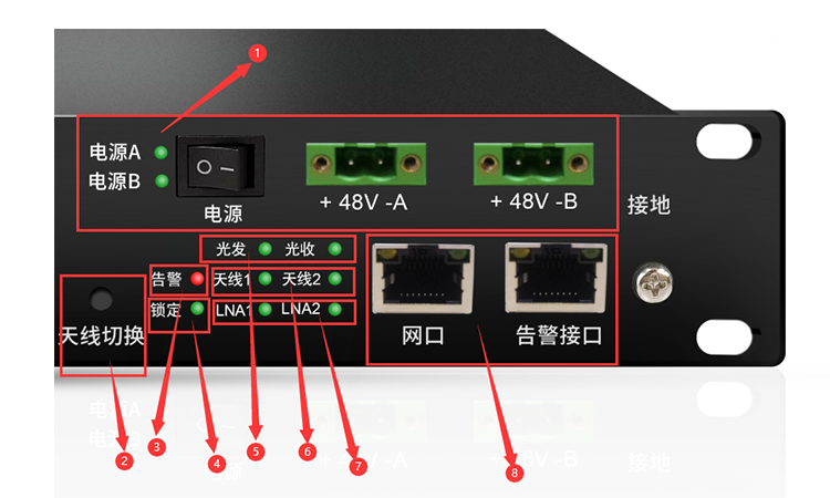
⑴ Power supply: Support dual 48V power supply and adopt dual power supply modules design. In the event of fault of any power supply module, standby module can be used to guarantee the normal running of equipment; the equipment provides burn-proof function so that the equipment parts won’t be burned out if the positive pole and negative pole of power supply are reversely connected.
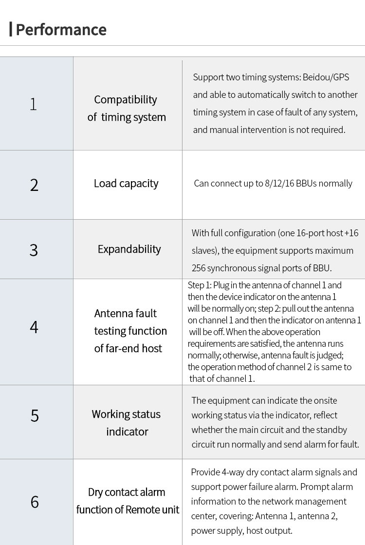
⑵ Antenna switch:Far-end host supports antenna switching by the antenna switch button, alarm reset and memory function. By long-pressing the key, the connection status of existing device ports are recorded. In case of device alarm, long-press the key to reset the device manually. Near-end host only supports memory and alarm function.
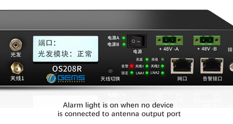
⑶ Alarm: Red alarm light will flash all the time unless two power supply units and two antennas are connected properly. Only after power supply and antennas are connected properly, the alarm light can be disabled by pressing down the antenna switch button for 5s.
⑷ Satellite lock indicator: When a satellite is locked, the satellite lock indicator is normally on.
⑸ Optical fiber indicator: The indicator is on, indicating the optical fibers are in normal use; the indicator is off in case of optical fiber fault.
⑹ Antenna indicator: When two-way antennas are connected normally, corresponding indicator will be normally on.
⑺ LNA indicator: When it is on, it indicates that LNA functions normally; when it is off, it means fault of LNA function and it’s required to check if device output is short circuited.
⑻ Network management alarm interface: Connect network management through RJ45 network interface to monitor the device; RJ45 interface is dry contact interface through which the device sends alarm for fault.
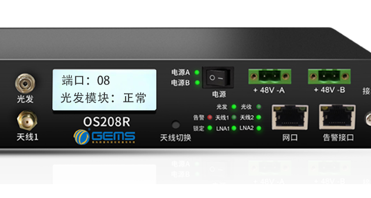
Select antenna mode actively: Select “Auto” or other antenna mode. The indicators on the panel will indicate the operation mode. If “Auto” mode is selected, the “Antenna 1” flashes green while the Antenna 2 is normally on; it’s same when “Antenna 1” mode is selected, the “Antenna 1” flashes green and the Antenna 2 is normally on; when “Antenna 2” mode is selected, “Antenna 2” green light flashes and “Antenna 1” is normally on; antenna mode can be selected by pressing keys on the device front panel. Press down the key “Antenna Switch” to switch between three antenna modes alternately. The LCD will display the antenna mode in use. When the optical module runs normally, you can check whether the optical module runs normally via the LCD screen or corresponding indicator. If the indicator is on, it means the module runs normally.
If antenna encounters open circuit or short circuit, the green light of “Satellite lock” on the front panel will be off and the red “Alarm” light flashes, giving warning. If the memory output port (BBU or slave) is disconnected, the red light on the front panel flashes and buzzer sends alarm sound.
Alarm: The red alarm light device will flash all the time unless two power supply units and two antennas are connected properly. Only after power supply and antennas are connected properly, the alarm light can be disabled by pressing down the antenna switch button for 5s.
Antenna indicator :When the lock indicator lights on, it means the satellite has been locked; when the antenna 1 indicator flashes, it reflects that antenna 1 is in use; it’s also same to antenna 2.The device LNA functions normally when the LNA indicator is on; when the indicator is off, it indicates LNA fault.
4-way Dry Contact Alarm Function (Far-end Host)
Power supply alarm: When the power supply is connected normally, pin 1 and pin 2 are closed. In case of open circuit or short circuit of any power supply, pin 1 and pin 2 are disconnected.
Output port alarm: The alarm of output port takes effects only with memory. After output port is connected normally, pin 1 and pin 3 are disconnected. If any port is disconnected or short circuited, pin 1 and pin 3 are closed.
Antenna port alarm: When antenna 1 is connected normally, pin 1 and 4 are disconnected; if the antenna 1 is disconnected or short circuited, pin 1 and pin 4 are closed; when antenna 2 is connected normally, pin 1 and pin 5 are disconnected; in the event of disconnection or short circuit of antenna 2, pin 1 and pin 2 are closed.
COM(comm on terminal)
2
Pin
Definition
1、8
Power alarm
3
Output port alarm
4
Antenna 1 alarm
5
Antenna 2 alarm
2-way dry contact alarm function (Near-end host)
Power supply alarm: When the power supply is connected normally, pin 1 and pin 2 are closed. In case of open circuit or short circuit of any power supply, pin 1 and pin 2 are disconnected
Output port alarm: The alarm of output port takes effects only with memory. After output port is connected normally, pin 1 and pin 3 are disconnected. If any port is disconnected or short circuited, pin 1 and pin 3 are closed.
COM(comm on terminal)
Pin
Definition
1、8
2
Power alarm
3
Output port alarm
Common Faults Troubleshooting
|
Fault |
Cause |
Handling Method |
|
Alarm light flashes |
Device interface is disconnectedand fault is not reset |
Check if antenna power interface is connected successfully, if the output is normal. Long press the key to reset the fault. |
|
Antenna indicator is off |
Poor connection of antennas |
Check if antennas are connected properly and if the interface is in good contact. |
|
LNA light is off |
Short circuit of input port |
Check the antenna input portand antennas for short circuit |
|
Buzzer alarm |
No reset after eliminating fault |
Long press the Reset key. |