Problems in the construction of 5G base stations
Problem 1
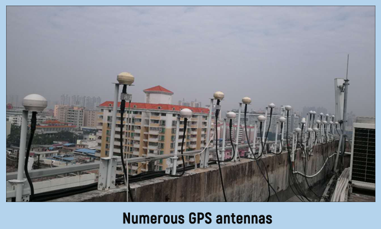
With the application of 4G and 5G, there tends to be multiple BBUs (base band unit) in a machine room. When there are excessive BBUs, numerous GPS antennas are required to be installed.
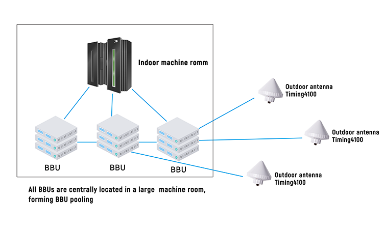
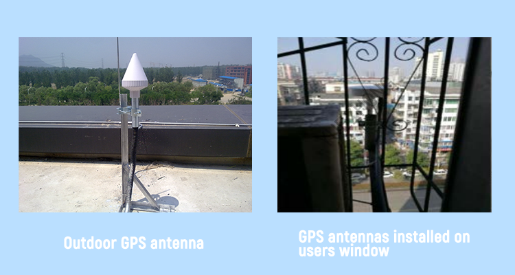
Excessive antennas will bring difficulty in cabling, and forced installation tends to cause signal interference, thus affecting the normal use of base stations; considering the shortage of roofing resources, installation of antennas is subject to the restriction by external environment. In some places, it’s impossible to set up or install GPS antennas, bringing great difficulty to construction.
Multichannel feeder lines involve large scope of engineering which leads to long time of delivery and an increase in costs. In addition, too many cables in the machine room will bring difficulty to later comprehensive maintenance.
Problem 2
Among many BBU machine rooms, a considerable proportion of machine rooms are not suitable for setting up GPS antennas and it’s required to introduce GPS signals of far-end machine room via optical fibers from adjacent machine rooms. In some machine rooms, the position for setting up antennas is too far away from the machine room (over 300m). Under such circumstance, traditional RF cables cannot satisfy transmission requirements.
Solution
I. To solve the problem of sharing GPS antennas by machine rooms, GEMS’s GPS clock synchronization distribution system can be adopted.
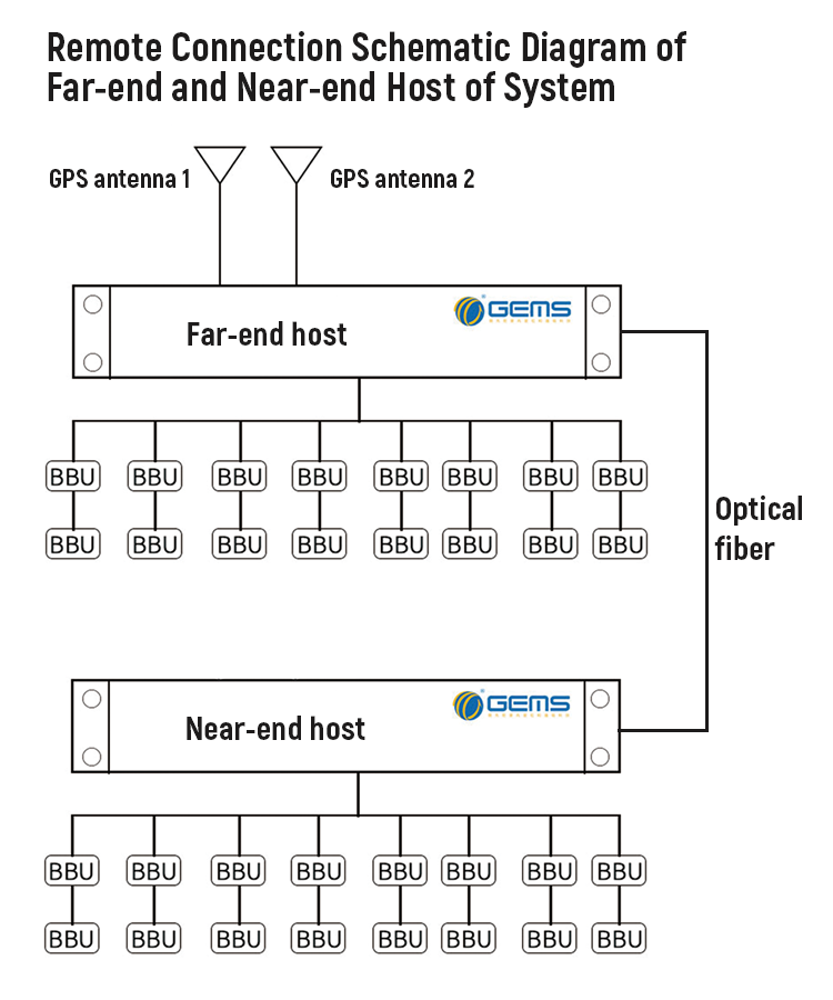
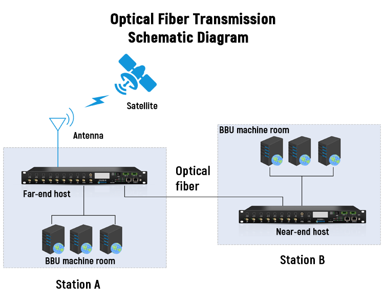
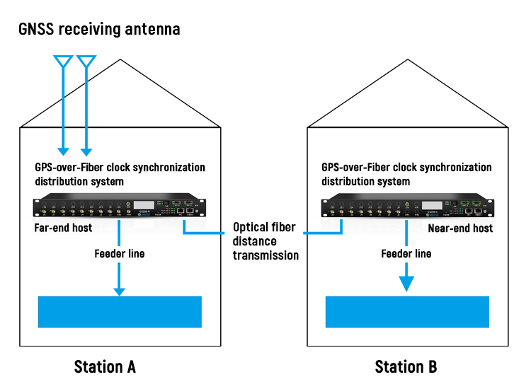
II. To solve the problem that antenna installation is restricted in machine room, GEMS’s GPS optical fiber transmission technique and remote fiber timing system solution can be adopted. GPS satellite antenna signals of a certain machine room at the far-end are transmitted to local machine room at near-end through optical fibers and then redistribution of RF signals is realized.
Application of GEMS’s GPS-over-Fiber Clock Synchronization Distribution System
GEMS’s GPS-over-Fiber clock synchronization distribution system (remote fiber timing distribution system) adopts intelligent shunting system and distributes the timing signals of GPS active antennas to multiple BBUs. Moreover, this system has been equipped with optical transmitter and receiver module for sending and receiving signals. In this way, when the host receives external GPS antenna signals, internal optical transmitter module receives the GPS signals, which will be transmitted to the optical receiver module of another remote host through remote fiber method when long-distance transmission is required so that the problem of limited transmission distance is solved. Besides, multiple hosts can share two GPS antennas by connecting the transmitting host to external GPS antennas.
I. System Description and Connection Schematic Diagram
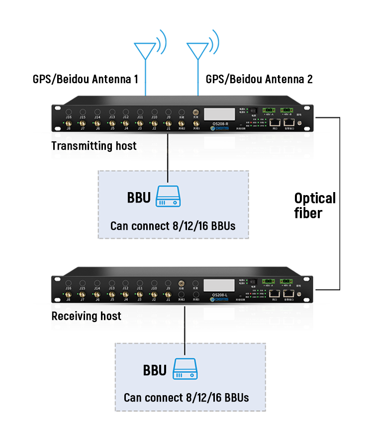
Cascade Mode Schematic Diagram of Optical Fiber System Host
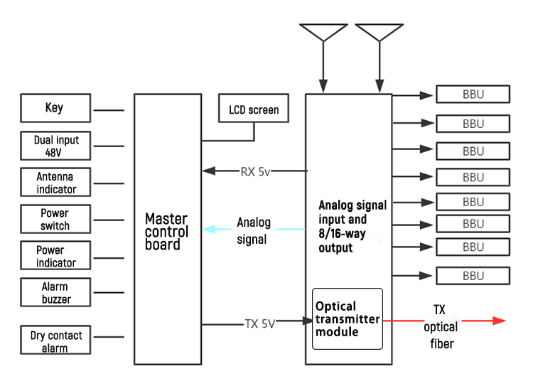
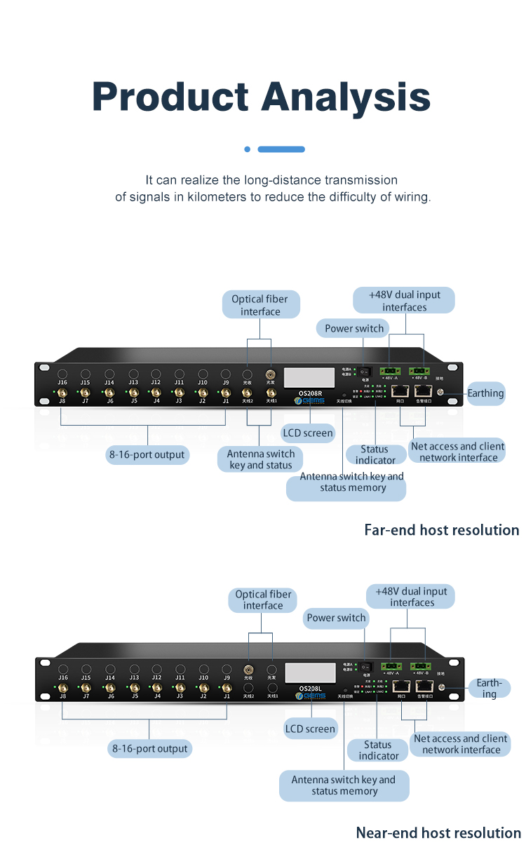
II. Far-end Host System (Optical Transmitting System)
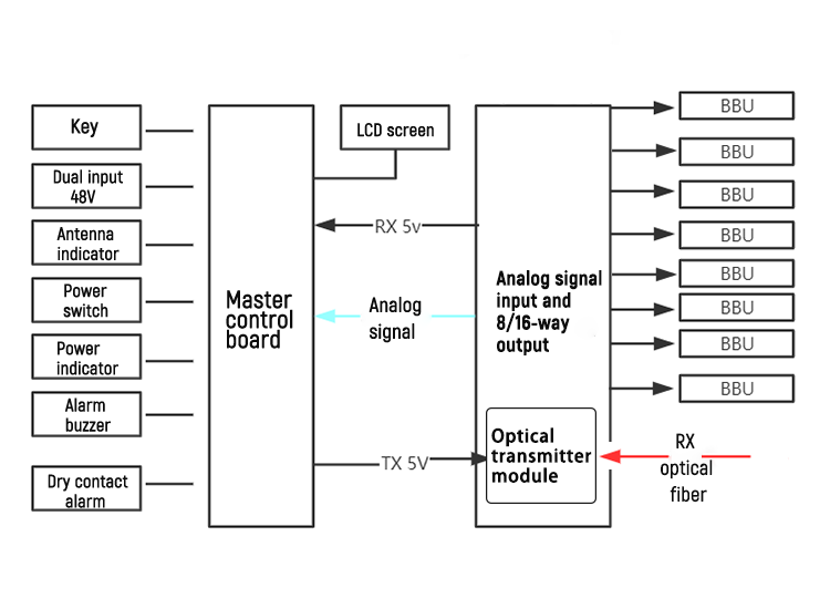
III. Near-end Host System (Optical Receiving System)
Product Description
This system consists of far-end host and near-end host. The far-end host receives input at two ends and possesses 1 to 8 optional optical fiber interfaces through which signals are transmitted to near-end hosts. The near-end host outputs signals to GPS device through 1-8/16 ports. The optical fiber signals received by near-end host from the far-end host are converted into GPS satellite signals and then amplified and distributed to the output ends. At the same time, the output port provides GPS signals to 8/16 ports.
After entering GNSS signal system management terminal and setting IP, this system can display the connection status of each port, number of visible GPS satellites and C/No value, number of visible Beidou satellites and C/No value, position, etc.
Optical fiber interface is used as independent interface for signal transmission between far-end host and near-end host via optical fibers.
Application in Complicated Environments
1.It is suitable for base station pooling, subway, transportation hub and other large distribution scenarios, and can significantly save costs and achieve the purpose of fast deployment;
2.Convenient for construction in scenarios where cables are disordered in the machine room, there are many antennas in the air and cabling is restricted by roofing and shaft;
3.With strong compatibility, this system supports base station devices from various mainstream manufacturers;
4.High accuracy and intelligent running;
5.High stability, dual power supply, dual antennas and automatic switching reduce equipment maintenance;
6.Self-timing of time source and LNA backup testing enhances the reliability of network;
7.Solve the problem that it’s impossible to install antennas under special environment in a certain station.
Advantages of GPS-over-Fiber Clock Synchronization Distribution System
1.Use and installation engineering of antennas are significantly reduced
2.By amplifying the input signals, the problem of limited distance of feeder line is solved.
3.Simple cables in machine room, convenient to maintain, dry contact and multiple monitoring methods of network cables.
4.Reduction of the requirements of BBU on GPS roofing space.
5.Long-distance optical fiber transmission doesn’t require that GPS antennas are installed in each base station, thus saving a great deal of installation work and greatly improving the base station construction efficiency.