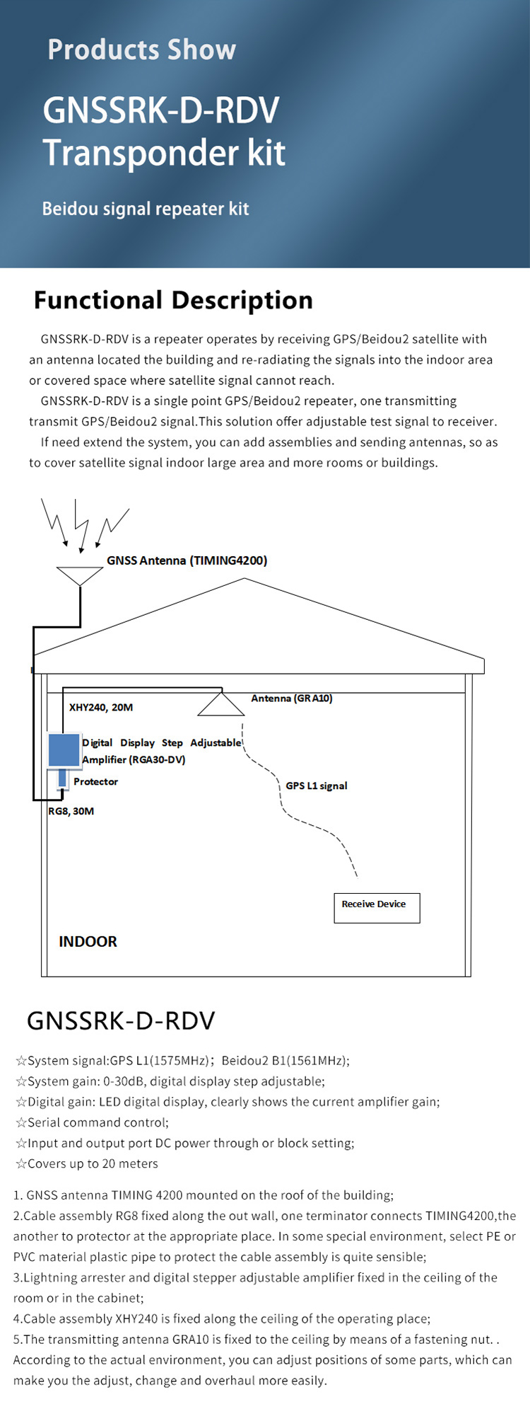
1.Functional Description
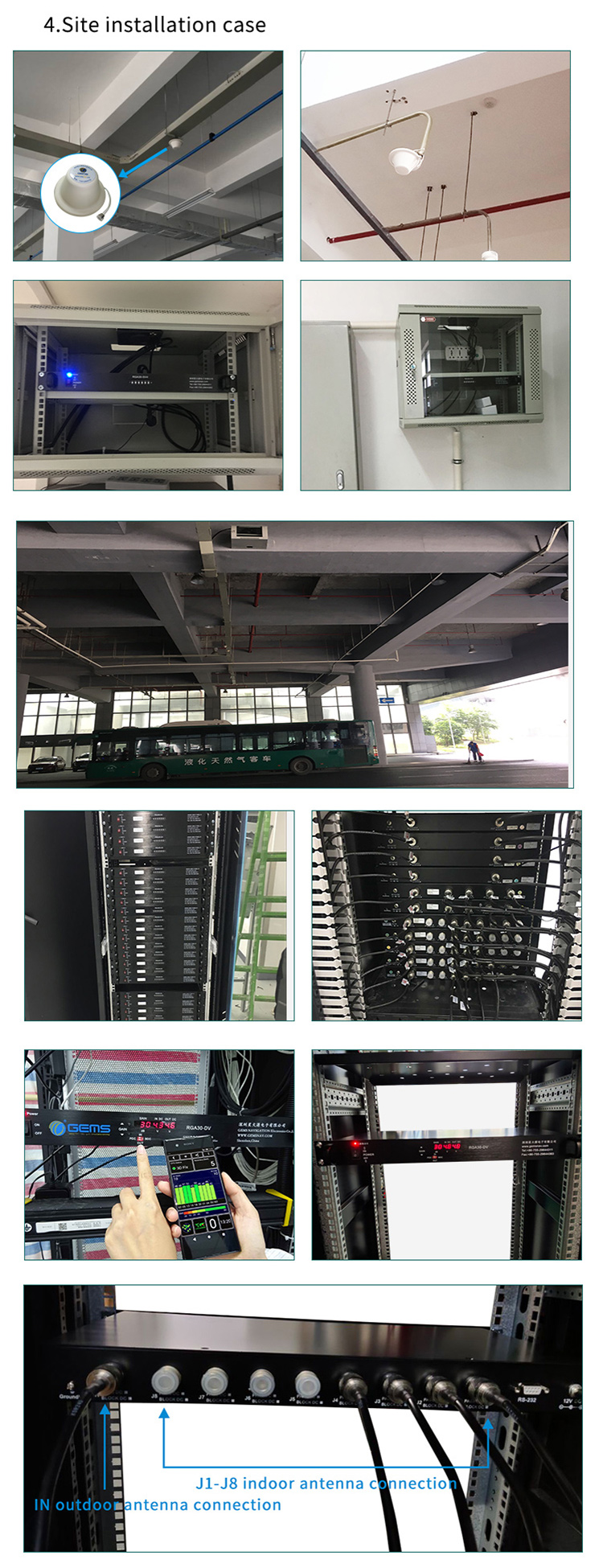
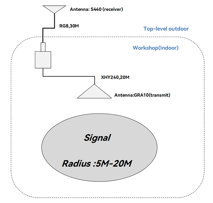
GNSSRK-D-RDV is a repeater operates by receiving GPS/Beidou2 satellite signals with an antenna located outside the building and re-radiating the signals into the indoor area or covered space where satellite signal cannot reach.
GNSSRK-D-RDV is a single point GPS/Beidou2 repeater, one transmitting antenna transmit GPS/Beidou2 signal. This solution offer adjustable test signal to receiver.
If need extend the system, you can add assemblies and sending antennas, so as to cover satellite signal indoor large area and more rooms or buildings.
2. Typical Application
For testing the cell- phone with GPS/Beidou2 , PND, car
navigators, tracker, survey products, etc.
Car parks, lab, aviation manufacturing hangar, trade shows, Emergency-, safety
vehicles, public transportation etc.
3. Standard Configurations
The cable components can be selected according to the customers' environment and can communicate with our technicians.
4. Topological (Under standard configuration)
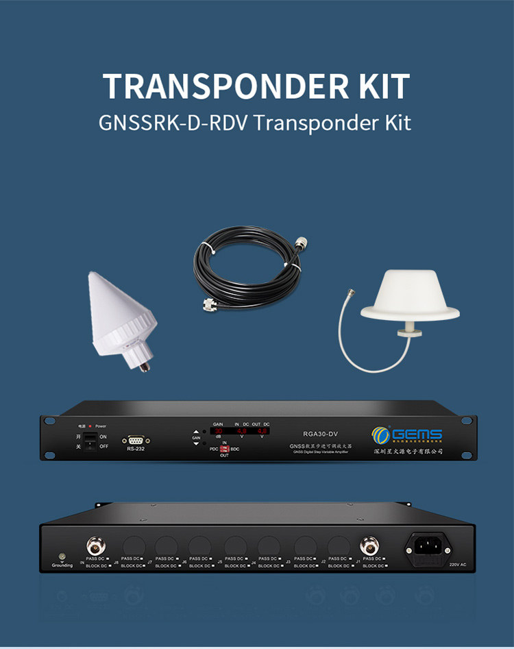
5. Kits include
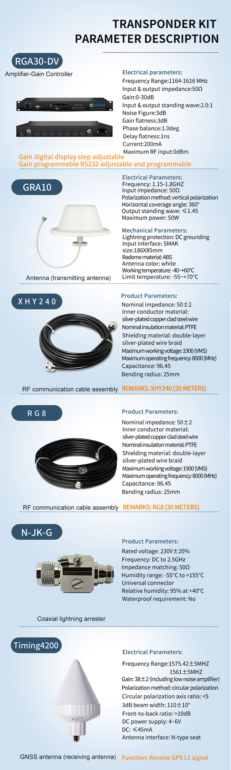
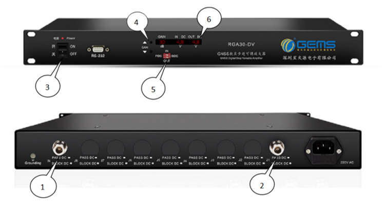
Used to adjust system gain, 0-30 dB adjustable, you can control when needed. The input and output can be set to energize 5V DC or not energized.
The system power supply voltage is 220V.
①and②are RGA30-DV input and output.
③For power control switch. System power-on when allocated to upward, opposite, system stops working.
④ For the gain adjustment button, you can adjust the gain size, you can adjust the controller gain increase or decrease. (Through the GAIN button to adjust. UP to the big, down to small.)
⑤For the input and output power state setting, IN for the input, Out for the output, PDC that power, BDC that does not power.
⑥For the digital display, showing the current gain value of the amplifier, and the voltage of the input and output ports.
Electrical Specifications, Operating Temperature -40 to 85°c
|
Parameter |
Conditions |
Min |
Typ |
Max |
Units |
|
Freq. Range |
In- Output ports, 50Ω |
1164 |
|
1616 |
MHz |
|
In &Out Imped |
In, all output ports |
|
50 |
|
Ω |
|
Gain 1207MHz 1227MHz 1561MHz 1575MHz 1609MHz |
In- Output ports -45dBm Input Level |
|
0~30 |
|
dB |
|
(0~30)-1.5 |
0~30 |
(0~30)+1.5 |
|||
|
(0~30)-1.5 |
0~30 |
(0~30)+1.5 |
|||
|
(0~30)-1.5 |
0~30 |
(0~30)+1.5 |
|||
|
(0~30)-1 |
0~30 |
(0~30)+1 |
|||
|
(0~30)-1.5 |
0~30 |
(0~30)+1.5 |
|||
|
Input SWR |
|
|
|
2.5:1 |
- |
|
Output SWR |
|
|
|
2.5:1 |
- |
|
Noise Figure |
|
|
|
3 |
dB |
|
Gain Flatness |
|
|
|
3 |
dB |
|
Current balance |
|
|
|
0.5 |
dB |
|
Phase Balance |
|
|
|
1.0 |
deg |
|
Group Delay Flatness |
|
|
|
1 |
ns |
|
Current |
Pass DC, No Powered configuration, DC input on Out Port |
|
|
250 |
mA |
|
Max RF Input |
Max RF input without damage |
|
|
0 |
dBm |