Description
The GS14i IS a high performance GPS signal splitter that can be configured to monitor the GPS antenna current , providing and alarm indication if the antenna is not operating to spec. The GS14i also features an optional antenna DC bias “Pick‐&Choose” circuit which allows for active antenna DC input to be applied to any or all of the RF outputs, With this option ,one DC voltage will be chosen to power the antenna while the other input will be switched to DC loads, if the selected DC bias input should fail, the DC bias will be automatically switched to another DC input so as to ensure an uninterrupted supply to the active antenna. The GS14i man be configured as a passive or an active device, giving the network engineer the flexibility to specify the device gain and port‐to‐port isolation, The GS14i may also be ordered with surge protection on all five ports and in a sealed housing sufficient for many years of Operation in external environments.
Specification
Electrical specification, operating temprature -40 to 85 ℃。
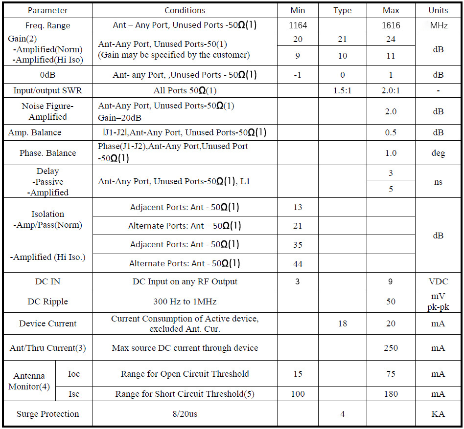
Note: (1) Note that proper RF performance, the GS14i must have all RF ports terminated into a 50 ohm coaxial cable system or a 50 ohm load.
(2) Custom gain option available.
(3) Maximum current available from the DC source through the GS14i when output of GS14i is short circuited.
(4) Open circuit and short circuit current(IOC, ISC) may be specified by the customer within the specified range.
(5) In-rush current shall not exceed 3A or exceed Isc for greater than 1ms.
Operational Description
The GS14i splitter requires that a DC voltage be applied to one or more of the RF output ports by ways of the RF connector center conductor.If DC voltages are applied to more than one of the RF output ports,the GS14i pick‐&‐chose circuit will choose one of these DC input to power the active circuitry of the GS14i and will also pass this DC voltage through the splitter to the center conductor of the RF input port.The DC voltage available on the RF input port can then be used to power the application’s active antenna.The DC voltages applied to the RF outputs that are not chosen by the pick‐&‐choose circuitry will be automatically switched through an RF choke to 200Ohm DC loads.The DC voltages may be applied to any or alll of the RF outputs;however,the pick‐&‐choose circuit will always select the DC voltage ont the lowest numbered RF port that has a DC voltage applied to power the GS14i and the application’s antenna.If the choosen DC input were to be removed or fail,the pick‐$‐choosen circuit will automatically switch to the next higher mumbered RF port to which a DC voltage is applied.
The GS14i has the option as either a passive devide, of to be ordered with amplification. If the amplified option is chosen, additional options are available for specifying the amplifier gain and the poer-to-port is isolatin . Amplified versiona of the GS14i that also include the high Isolation option do not require 50 ohm termination on unuesd ports in order for the splitter to peratte properly. Passive versions or amplified versions without the high solation option always require 50 ohm terminations on unused ports for proper operation.
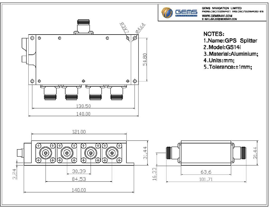
Mechanical