【Description】
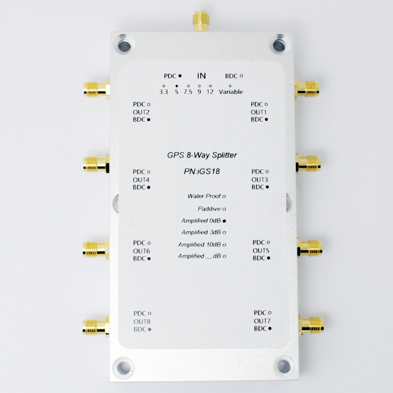
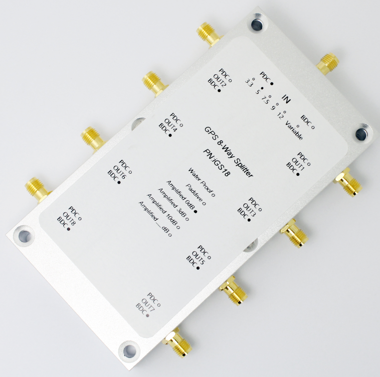
The iGS18 GPS Splitter is a one‐input, eight‐output GPS device. This product typically finds application where an input from an active GPS roof antenna is split evenly between four receiving GPS units. In this scenario, the iGS18 can be configured to pass DC from an RF output to the antenna input port in order to power an active GPS antenna on that port. The others outputs would feature a 200 Ohm DC load to simulate an antenna DC current draw for any receiver connected to those ports. Individual iGS18 work independently as a separate product.iGS18 can control the 8 output ports power state, can detect the output port voltage.
【iGS18 Characteristic】
▷Programing Control the DC Pass or Block All Ports;
▷Monitoring The Voltage of All The Ports;
▷Connecting the PC Via The RS232 Port;
▷Design For R&D and Manufacture Test;
▷Full GNSS Band:GPS/GLONASS/Beidou/Galileo/IRNSS/QZSS/SBAS/NAVIC;
▷Frequency Range:1164~1616MHz;
▷Gain(amplified):0dB ~ 10dB(Be specified);
▷DC Power Adaptor(Standard);
▷High Isolation: >30dB;
▷Low Noise Figure: <2.5dB
▷Avaible In TNC, SMA, BNC and N Connectors.
.png)
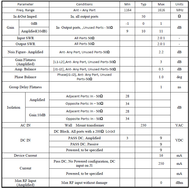
【Specifications】
Electrical Specifications, Operating Temperature -40 to 85 ℃.
【Operation Instructions】
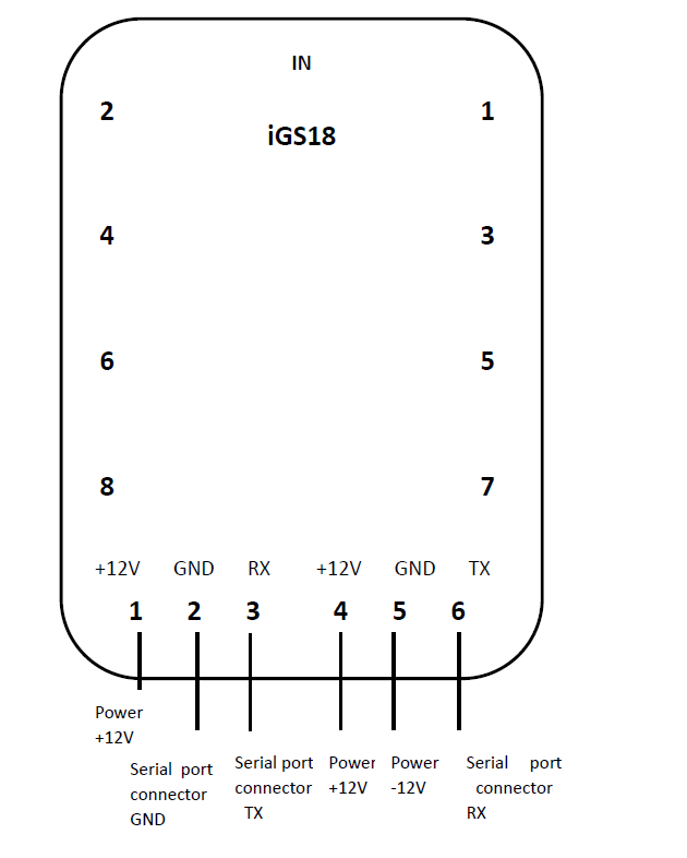
1.Connect serial port
Note: RXD product iGS18 serial port connector TXD; product TXD connected to the serial port connector RXD.
2.Serial port parameters
Open serial debug assistant software:
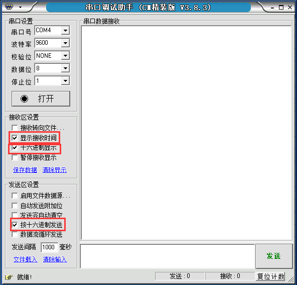
Press table setting parameters:
|
Set items |
Default Parameter |
|
Band Rate |
9600 |
|
Check bit |
nothing |
|
Data bits |
8 |
|
Stop bit |
1 |
|
Pin definition |
|
NOTE: You must insert the serial connector can see the serial number.
3.Calculation of power off and read voltage instructions
STX: 0x02 frame start flag;
DLE: 0x10 transcoding, for use in the frame start or frame end flag before, if DLE equal to the value data appears in the frame, the data retransmission protocol requires one to represent distinction, that is represented by two consecutive DLE data, a DLE represents the transcoding;
CMD: Communication instruction data type, including data communication instruction (0xF1) and
control commands (0xF2) of two types;
Parameter: CMD communication instruction data content, data length;
ETX: 0x03 frame terminator flag (not included in the back of the validation data);
BCCL: binary BCC check code low 8;
BCCH: binary BCC code high 8.
Then DLE, STX and ETX three hexadecimal constant, which is the first 1,2,5,6 These four numbers are the same, you need to calculate the CMD, parameters, BCCH and BCCL four hexadecimal number.
【Schematic diagram of serial connection】
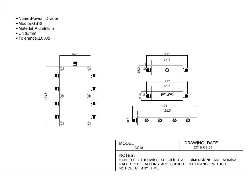
【Mechanical】